You are standing in the aisle of your local electronics store, staring at two projectors that look nearly identical but…
Read More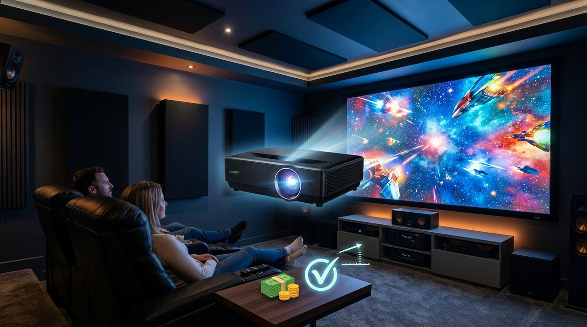
You are standing in the aisle of your local electronics store, staring at two projectors that look nearly identical but…
Read More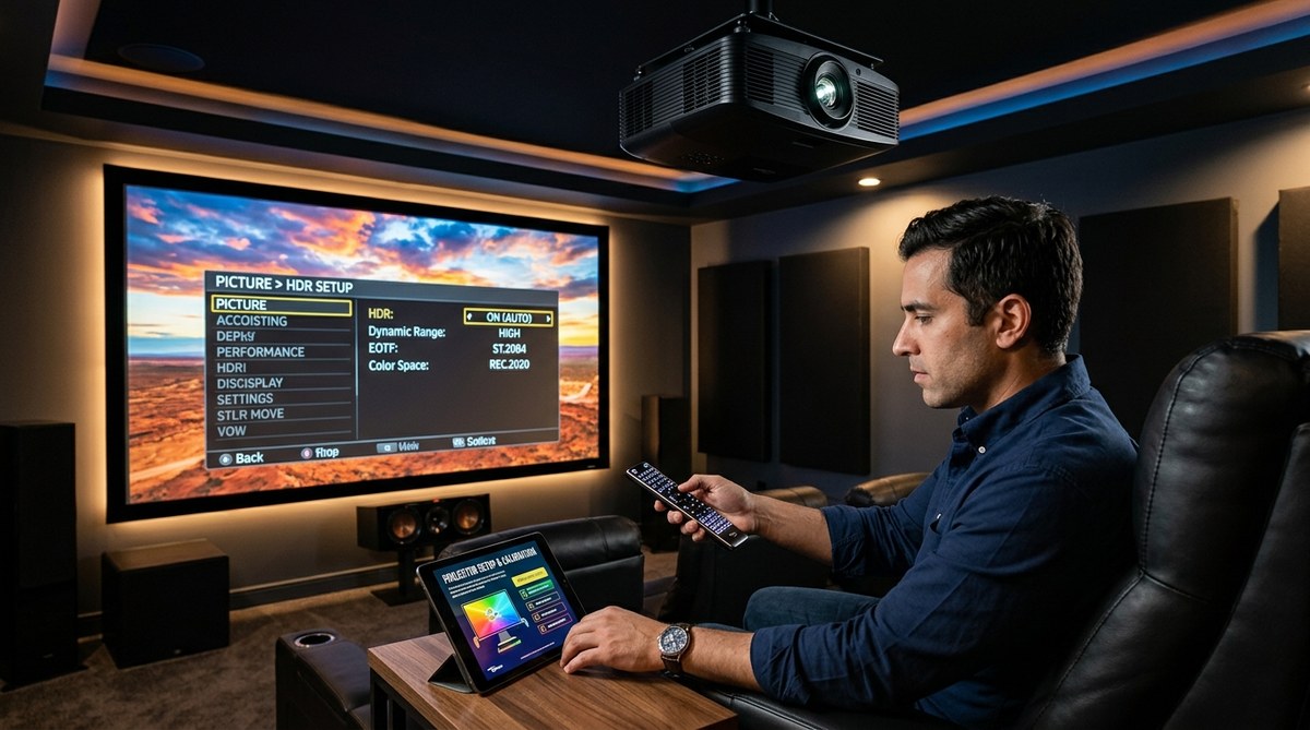
HDR on a projector can feel like a different beast compared to a TV. You crank up a bright HDR…
Read More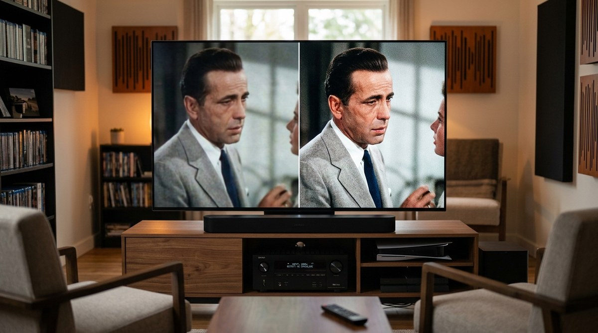
You finally unboxed that 4K TV you waited months for. You grab your favorite DVD from 2005, press play, and…
Read More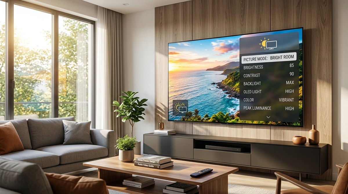
Looking to enjoy your favorite shows and movies in a bright room without sacrificing picture quality? Many people struggle with…
Read More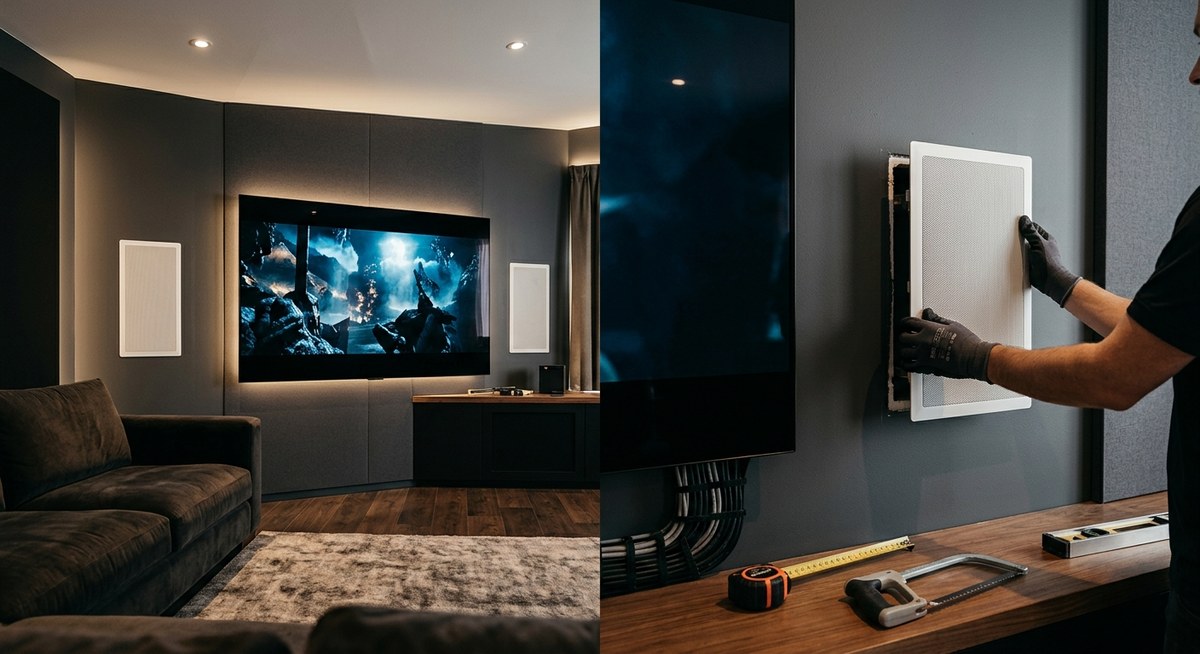
Getting a home theater that looks stunning and sounds incredible starts with proper speaker placement. Installing in-wall speakers is a…
Read More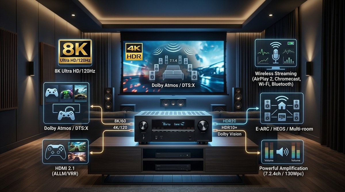
Looking to upgrade your home theater in 2024? The right receiver can transform your movie nights and gaming sessions. But…
Read More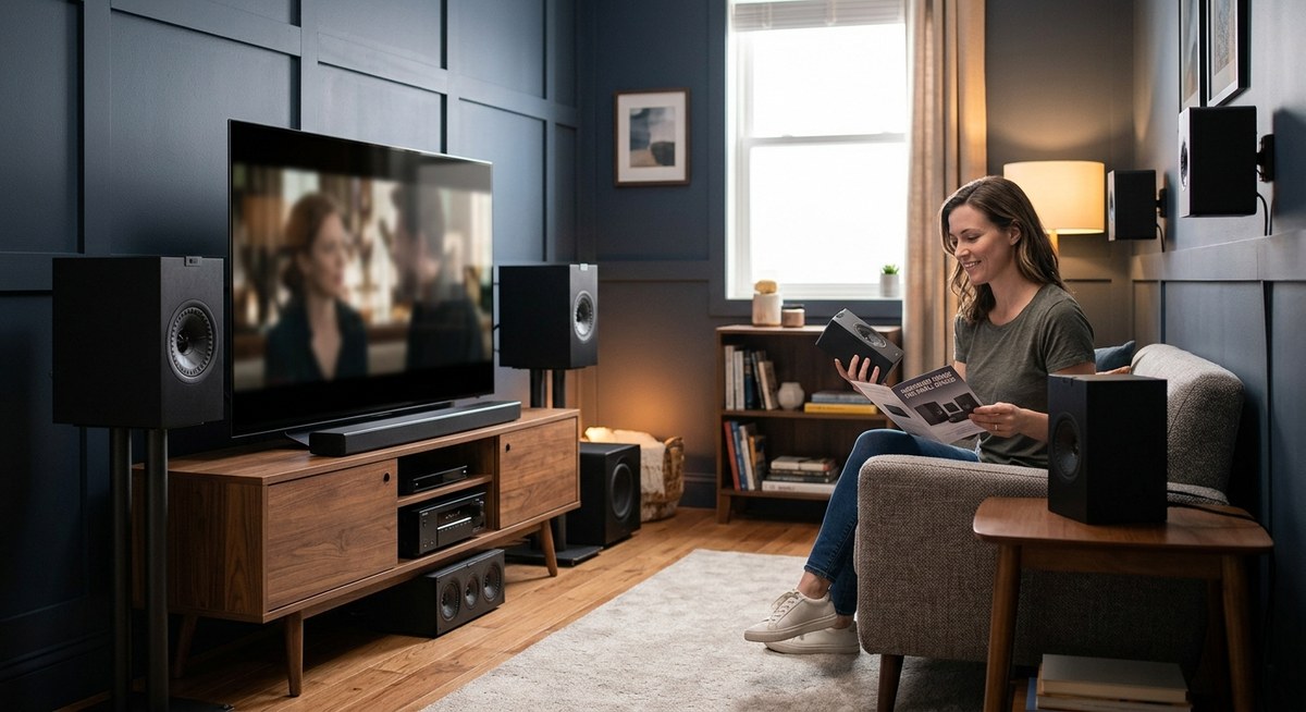
Getting great sound in a small room can feel like a challenge. You want immersive audio without cluttering your space…
Read More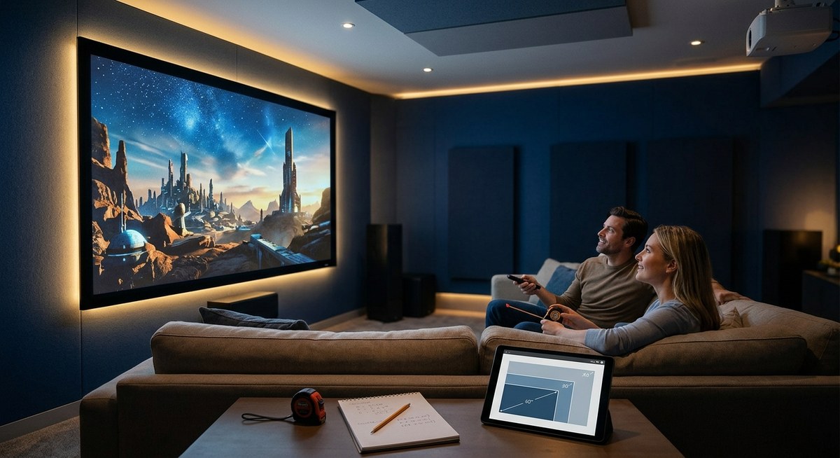
Looking to create the ultimate home theater experience? Picking the right projector screen size is key. It influences picture quality,…
Read More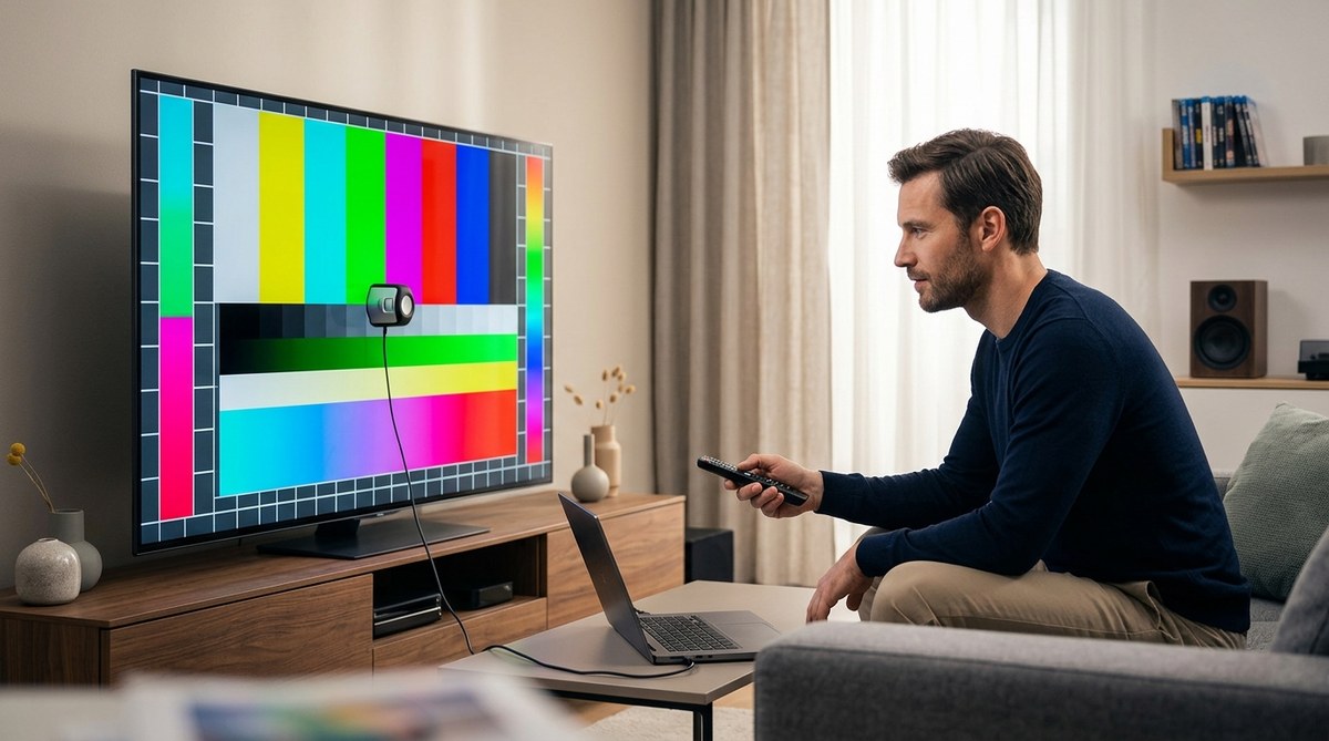
Getting the most out of your television means more than just turning it on. Proper color calibration transforms your viewing…
Read More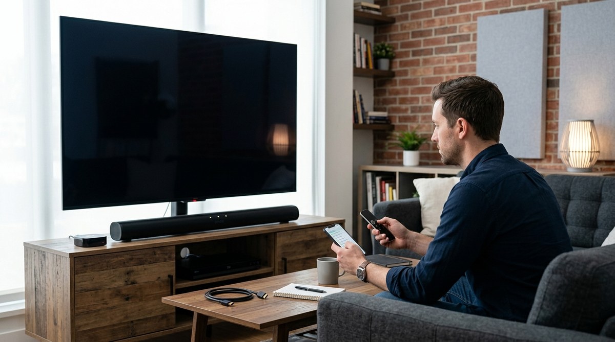
If your TV turns on and you can hear audio but the screen remains black, it can be frustrating. You…
Read More