Looking to upgrade your home theater in 2024? The right receiver can transform your movie nights and gaming sessions. But…
Read More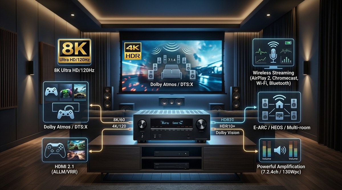
Looking to upgrade your home theater in 2024? The right receiver can transform your movie nights and gaming sessions. But…
Read More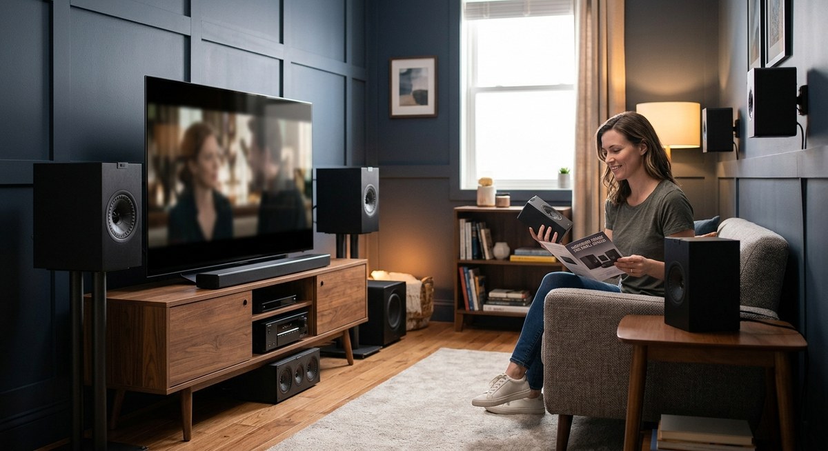
Getting great sound in a small room can feel like a challenge. You want immersive audio without cluttering your space…
Read More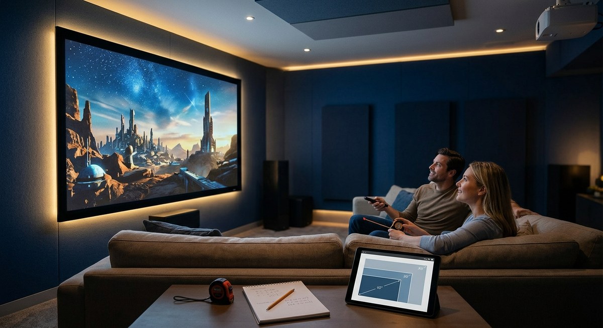
Looking to create the ultimate home theater experience? Picking the right projector screen size is key. It influences picture quality,…
Read More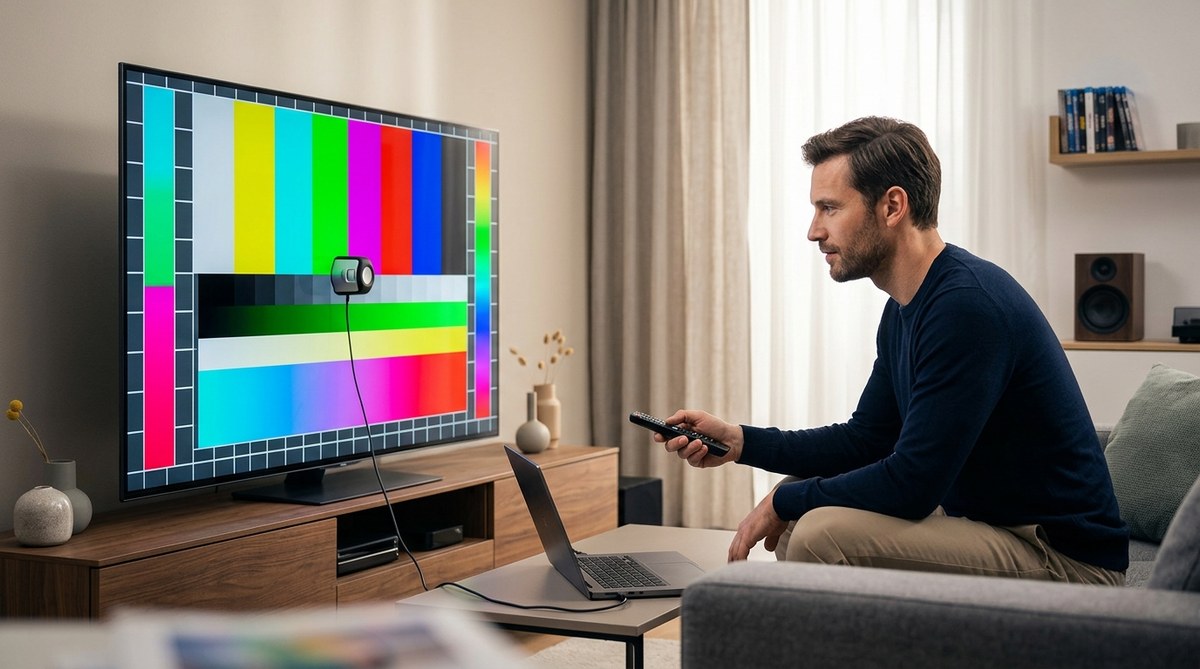
Getting the most out of your television means more than just turning it on. Proper color calibration transforms your viewing…
Read More
If your TV turns on and you can hear audio but the screen remains black, it can be frustrating. You…
Read More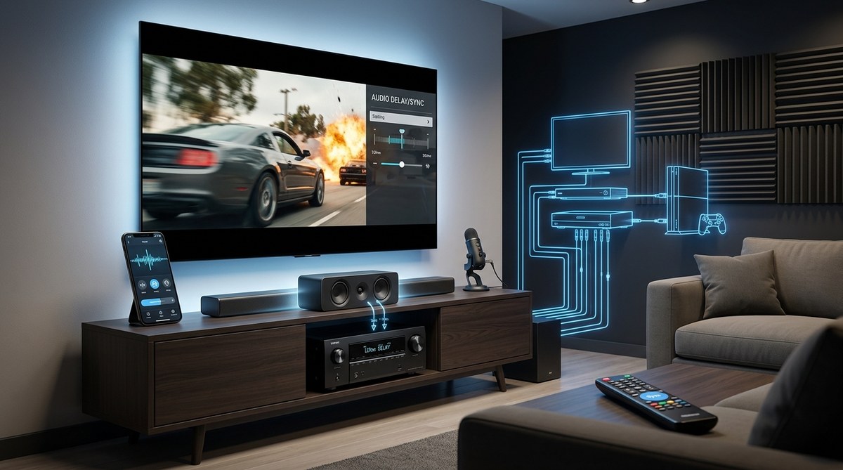
When your home theater experience feels off because the sound doesn't match the picture, it can be frustrating. Audio delay…
Read More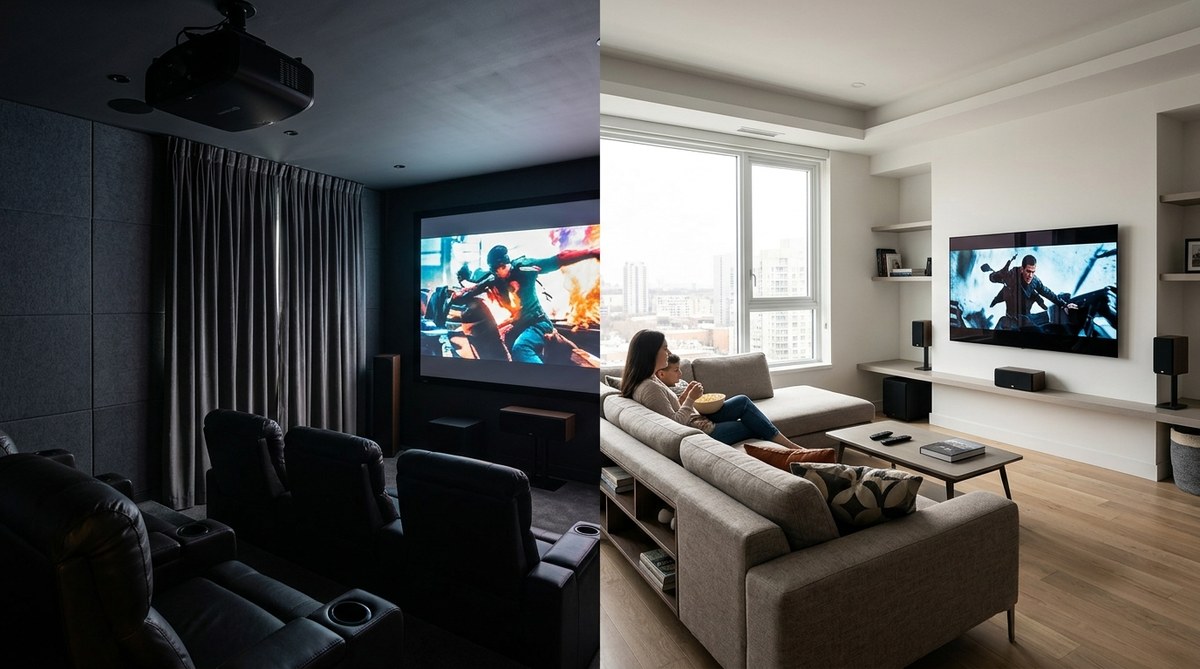
Creating the perfect media and entertainment environment at home depends on your lifestyle, space, and priorities. Should you carve out…
Read MoreHome theater enthusiasts understand that achieving perfect sound requires more than just high-quality speakers and an impressive receiver. Room acoustics…
Read More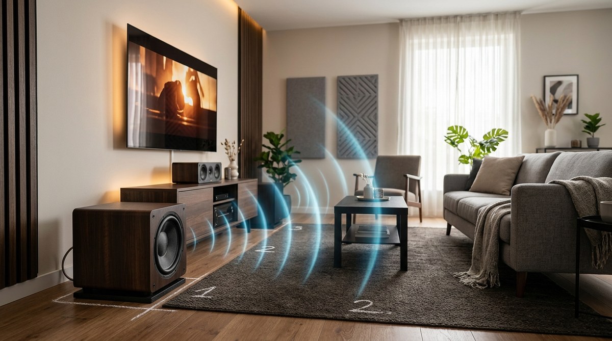
Getting the most out of your home theater or audio system means paying attention to your subwoofer's placement. Proper positioning…
Read More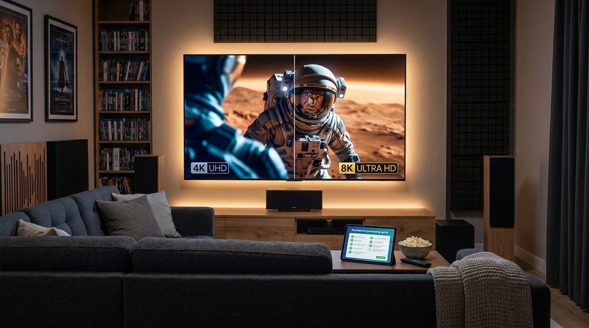
Thinking about upgrading your home theater setup? You might be wondering whether a 4K or 8K TV is the right…
Read More